Located in Northwest OHIO
Manufacuring CDI systems and CNC parts

INSTALLING AND TIMING THE HALL SENSOR
LEE HODGSON 9 CYLINDER RADIAL ENGINE DISTRIBUTOR

click on link for full size photo1-Parts required to install the Hall Sensor and time the distributor. If you are handy with a soldering iron you can download a schematic for a simple timing light circuit or purchase our timing light hall tester tool.
Timing Light schematic
click on link for full size photo6-WRONG pole of magnet. LED did not go off. If the LED does not go off with either pole of the magnet facing it then it is either defective or the part no. is not facing up. Only the side with the part no. is sensitve to the magnet.
click on link for full size photo2-Insert hall sensor through base of distributor and bend lead  90 degrees as shown. NOTICE the part no. on the sensor is facing up. You will have to heat the wires with a BIC lighter and hold it until they cool. DO NOT over heat the wires, keep the flame at least 1 inch from the wires. click on link for full size photo7-Marking NO.1 spark plug location.
click on link for full size photo3-Pull the lead back through the distributor base until the sensor is resting  flat on the bottom of the distrubutor base. click on link for full size photo8-Marking Hall Sensor location.
click on link for full size photo4-Attach the timing light to the hall sensor lead and a 4 cell battery pack to the 2 wire battery connector. Notice when power is applied the LED is on. click on link for full size photo9-Timing light LED is off. This indicates the hall sensor is seeing the magnet.
click on link for full size photo5-Checking for correct magnet polarity. The sensor is only triggered by the SOUTH pole.
LED is off so the south pole of the magnet is on the sensor. Notice the part no. on the sensor must be facing up.
click on link for full size photo10-Turn the rotor clockwise until the timing light LED just comes ON. Timing the distributor at this location will position the rotor contact, part #102, page 192, exactly in the middle of the NO.1 spark plug pin. This eliminates arcing to adjacent terminals.


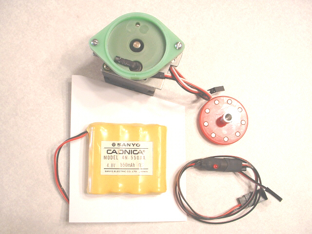
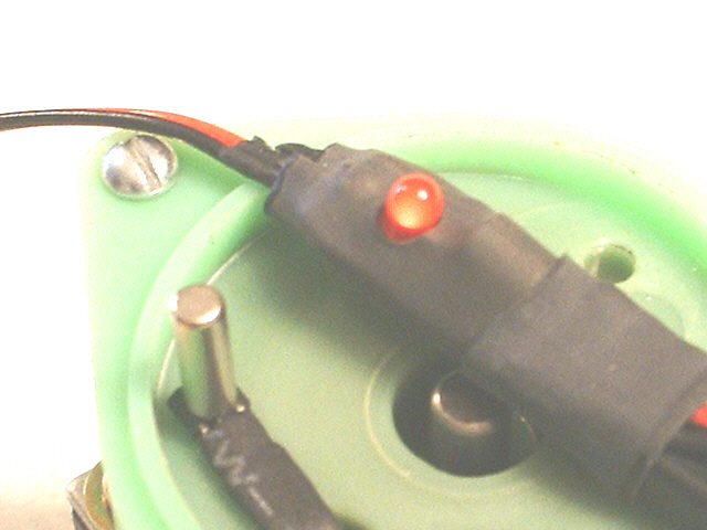
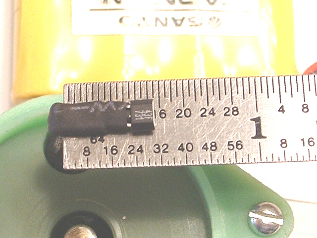
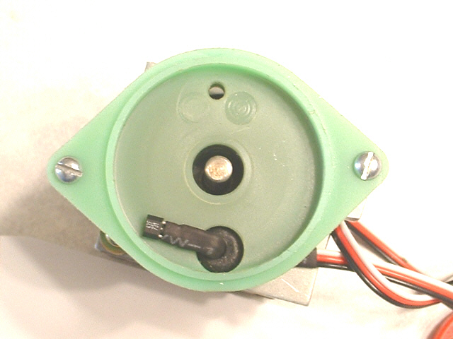
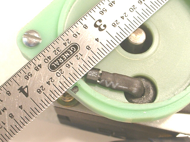
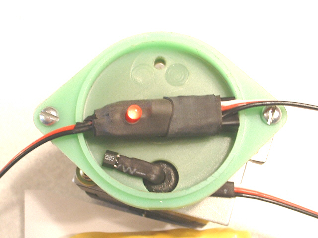
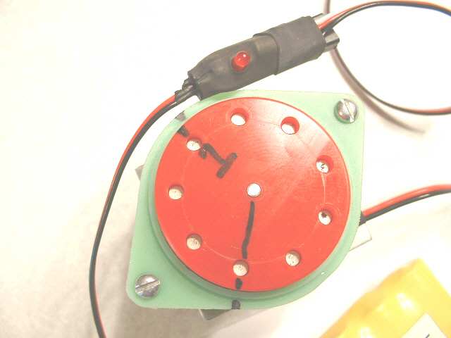
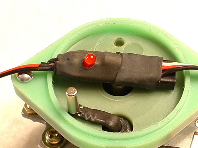
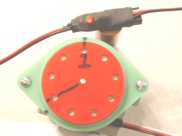
YOU WILL NOTICE A COUPLE OF FEATURES THAT ARE NOT CORRECT AS PER THE PRINTS:


The first item is the extra hole, photo #3, in the base of the distributor, the 2nd is the rotor is drilled all the way through for the magnets.
The hole in the distributor base corresponds to the hole location of the magnet in the rotor. By installing only 8 of the 9 magnets I was able to use the 9th hole
to locate the rotor at the NO.1 spark plug position and adjust the hall sensor until the timing light LED just comes on. This makes timing the distributor much quicker.
The 2nd item is the rotor. I did not make the rotor the proper thickness and drilled the holes all the way through because I intend to use this assembly for display.
The RED rotor in the photos was fabricated strictly for holding the 9 magnets and as a visual aid. In photo #3 you can see a shaft in the hole where the bushing should be.
The reason there is no bushing was to mount the distributor on top of  a small stepper motor which will drive the rotor  when it is on display.


About Us | Contact
Home Page


This page and all content is Copyright © 2004-2008,   S/S Machine & Engineering LLC.   All rights reserved.